When you boil them down to the most fundamental components, pumps are made up of two components:
- An impeller which creates velocity through rotation,
- And a casing which converts velocity into pressure.
There are different types of impellers and different types of casings. The way that different types of impellers and casings are combined produces all of the different types of pumps.
Types of Pump Casings
There two basic types of pump casings: volutes and diffusers.
Whether we’re talking about volutes or diffusers, what all casings have in common is that they are designed to take energy in the form of velocity and convert it into pressure.
Volutes
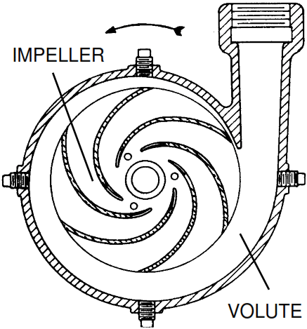
Volutes are designed to capture the velocity of liquid as it enters the outermost diameter of an impeller and convert the velocity of the liquid into pressure.
In the picture to the right, notice that the impeller is not located in the center of the volute. This is intentional. The portion of the volute that extends closest to the impeller is called the cutwater.
You will notice, that starting from the cutwater and proceeding in a counter-clockwise fashion, the distance between the volute and the impeller increases gradually. This has the effect of causing pressure to build within the volute as the distance increases. Once the point of greatest separation is reached – directly next to the cutwater moving in clockwise direction – the pressure is at its greatest, and water is forced out the casing when it encounters the cutwater.
Diffusers
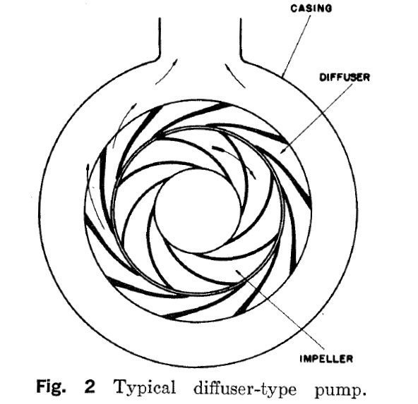
What a cutwater is to a volute, vanes are to a diffuser. While volutes only have one (or sometimes two) points where the edge of the casing approaches the edge of the impeller in order to begin building pressure, diffusers often have many vanes. In the case of the assembly drawing shown the diffuser contains 10 vanes as compared the volute casing which only has one.
Also, while an impeller is placed in the center of a volute, an impeller generally sits directly adjacent to a diffuser and pushes water into the diffuser vanes.
The basic function of a diffuser is similar to that of a volute. Diffuser vanes are positioned such that they begin close to the outer edge of the impeller and then gradually extend away from the impeller periphery.
Impellers
Impellers are usually classified in two ways:
- Specific Speed (Ns): The relationship between the amount of flow an impeller produces and the amount of head or pressure generated is called specific speed.
- Physical Design: Details such as whether an impeller is open or enclosed, whether it is single or double suction, and the way the impeller vanes are designed can all be used to describe and classify impellers.
Specific Speed (Ns)
Specific speed, also referred to as Ns, describes the relationship between how much flow an impeller produces and how much head it generates. When the specific speed of an impeller is calculated, the result is the speed at which a theoretical impeller of the same geometric design, but only 1″ in diameter, would have to operate to produce a flow of 1 gallon per minute and 1 foot of total dynamic head.
That sounds pretty confusing doesn’t it? To understand this concept, an example is called for.
- Impeller No. 1: Used in a flood control pump, this impeller generates a great deal of flow, but very little pressure.
- Impeller No. 2: Used in a boiler-feed pump, this impeller generates a great deal of pressure, but not very much flow.
Impeller No. 1 would have a high specific speed. This impeller design generates very little pressure relative to the amount of flow generated. As a result, a theoretical 1″ impeller of this design would have to operate at a very high speed to produce a flow of 1 GPM and 1 Ft of TDH.
Impeller No. 2 would have a low specific speed. This impeller design generates a great deal of pressure relative to the amount of flow generates. As a result, a theoretical 1″ impeller of this design could operate at a relatively low speed and produce a flow of 1 GPM and 1 Ft of TDH.
Below is a commonly-available graph that shows this relationship and how it affects impeller design.
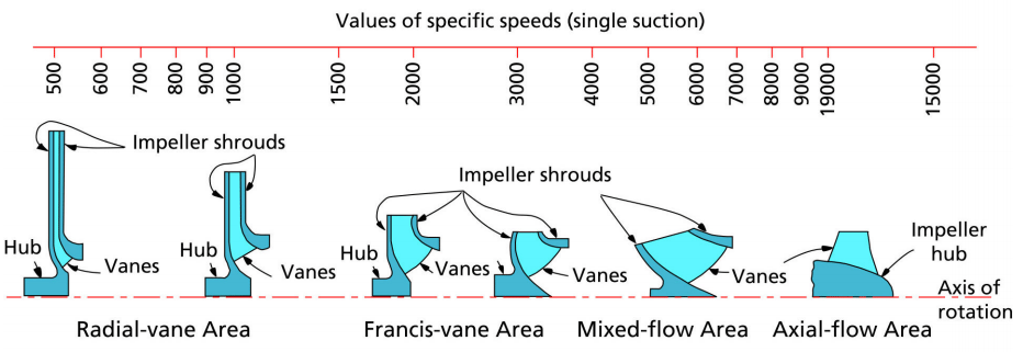
As you can see, impellers with lower specific speeds (low-flow but high-head designs) have very tight clearances. On the other end of the spectrum, you see impellers with high specific speeds (high-flow but low-head designs). These impellers, which are commonly called propellers once we reach the axial-flow field, have increasingly large internal clearances until you reach the axial-flow field in which case the impellers are completely open with no impeller covering or shroud.
Physical Design
Another way to classify impellers is according to the design. This method of classification is not unrelated to specific speed, and the specific speed of the impeller plays a large role in determining the physical design of the impeller.
Open vs. Enclosed
One differentiation in impeller design is the use or lack of a shroud or covering. Impellers with a top and bottom shroud are said to be enclosed impellers. Impellers without any shroud at all are said to be open impellers.
There are also single-shroud impellers in some specialty pumps, such as vortex impellers in solids-handling pumps. Such designs only have a top shroud and the impeller vanes are completely open to the liquid being pumped. Impellers of the single-shroud variety are ideally suited for applications where a large number of solids that might clog a shrouded impeller are present. However, single-shroud vortex impellers are much less efficient than enclosed impeller designs.
Single vs. Double Suction:
All of the impellers shown in the specific speed table above are of the single-suction design. This means that there is a single portion of the impeller that is designed to take in water. There are also impellers designed to take suction from both sides of the impeller. A drawing of this type of impeller can be seen below.
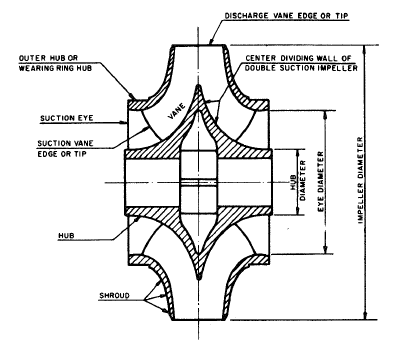
A double-suction impeller is a more balanced design than a single suction impeller because the two-sided design of the impeller balances the axial thrust loads imposed on the impeller and transmitted through the shaft to the pump bearings.
Vane Design
Some impellers have many vanes and tight internal clearances. These are typically intended for water service and generally fall between the radial-vane and francis-vane specific speed fields. Other impellers have just one or two vanes and large internal clearances. These types are often called solids-handling impellers and generally fall between the Francis-vane and mixed-flow fields. Still others are designed with a single vane and no lower shroud, or with vanes that do not extend very far down into product being pumped. These are called screw and vortex impellers respectively, and are intended for applications with a high concentration of solids. Finally, there are impellers will no shroud at all, top or bottom, such as what you see in the axial-flow field.
What Have We Learned?
There are two primary parts of every pump: an impeller and a casing. The impeller creates velocity and the casing converts velocity into pressure.
There are two primary pump casing designs. These two designs are volutes and diffusers.
There are many different impeller designs. The range of head and flow conditions they are designed to produce and the characteristics of the application for which they are intended dictate impeller design.
The combination of different types of impellers and casings produce the wide range of centrifugal pumps that are available.
Updated 12/16/2015
Great primer, refresher course
Very nicely explained.