Solids-handling pumps are commonly used for wastewater applications, raw-water intake pump stations, flood control, and dewatering.
What are Solids-Handling Pumps?
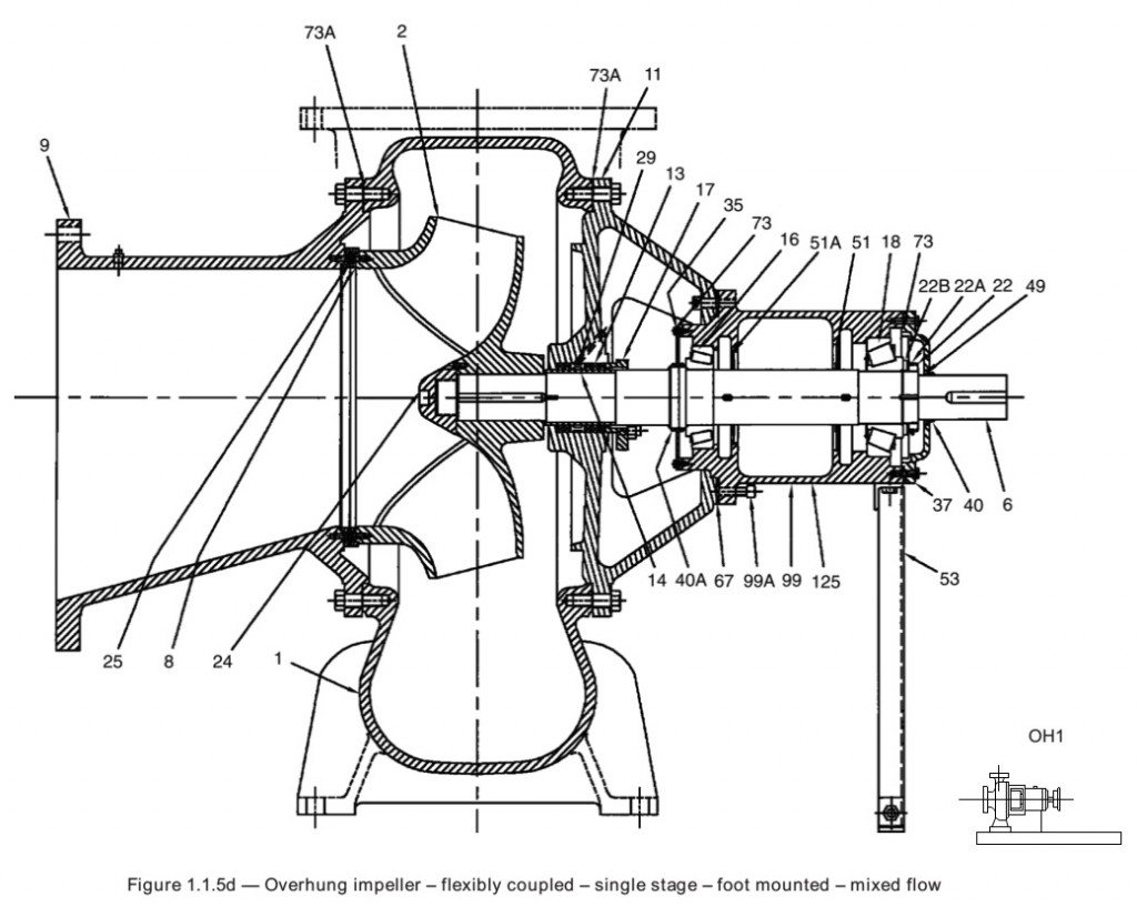
Solids-handling pumps are a centrifugal end-suction pump design. They combine a volute-type casing and an impeller with large internal clearances designed to pass the type of solids commonly seen in wastewater. Some specialty designs have open impellers called vortex or screw impellers which can handle larger and longer solids, but which sacrifice efficiency to do so.
Solids-handling pumps are typically construction of cast iron components, a steel pump shaft, and stainless steel wear rings and shaft sleeves. However, stainless steel impellers are a common upgrade due to the abrasive character of wastewater.
Solids-handling pumps should not be confused with the most common type of pump used in wastewater applications: submersible sewage pumps. While the hydraulic designs are quite similar, solids-handling pumps are not designed for operation while submerged. Instead, solids-handling pumps in a sewage application are installed in a dry-pit that is adjacent to a wet-pit – the sump where the sewage is located. A submersible pump, on the other hand, is usually just dropped right into the wet-pit.
Non-Clog vs. Solids-Handling
Some pump professionals refer to solids-handling pumps as non-clog pumps. However, as any good pump engineer or experienced pump operator will tell you: “You can clog anything”. As a result, the misnomer non-clog is best avoided in favor of the more accurate term solids-handling.
Pump Configurations
Solid-handling pumps are one of the more flexible pump designs in terms of layout options, and are commonly oriented either horizontally or vertically.
Frame-Mounted Solids-Handling Pumps
Frame-mounted or horizontally-mounted solids-handling pumps, such as the one in the diagram above, are mounted in the same fashion as typical end-suction pumps. The pump is mounted on a baseplate next to the motor, and they are coupled with a flexible coupling.
It is also common to belt-drive a solids-handling pump. Large solids-handling pumps often operate at relatively slow speeds. As a result, it often much more economical to use a set of properly-sized sheaves installed on the pump and motor shafts and a belt to adjust the operating speed of the pump to the desired speed than to use a motor designed for the pump’s operating speed.
A belt-driven arrangement employs a vertical offset to arrange the pump and motor in such a way that the sheaves line up and the belt can be used to connect the pump to the motor.
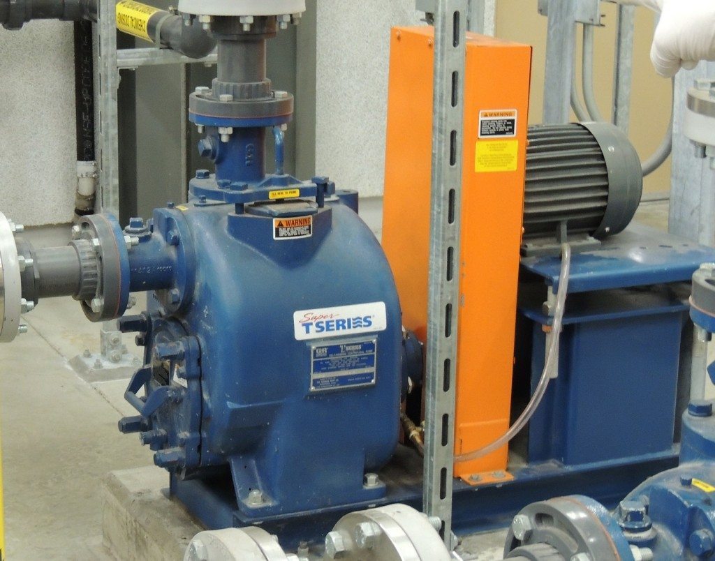
The blue pump in this image is a special type of solids-handling pump called a self-priming pump. Notice that the gray motor is positioned higher than the blue pump. This is so that properly-sized sheaves can be installed on the pump and motor shafts, and a belt can be installed between them. The belt is then covered with a guard, which in this case is the bright orange metal cover between the pump and motor.
Vertically Mounted Solids-Handling Pumps
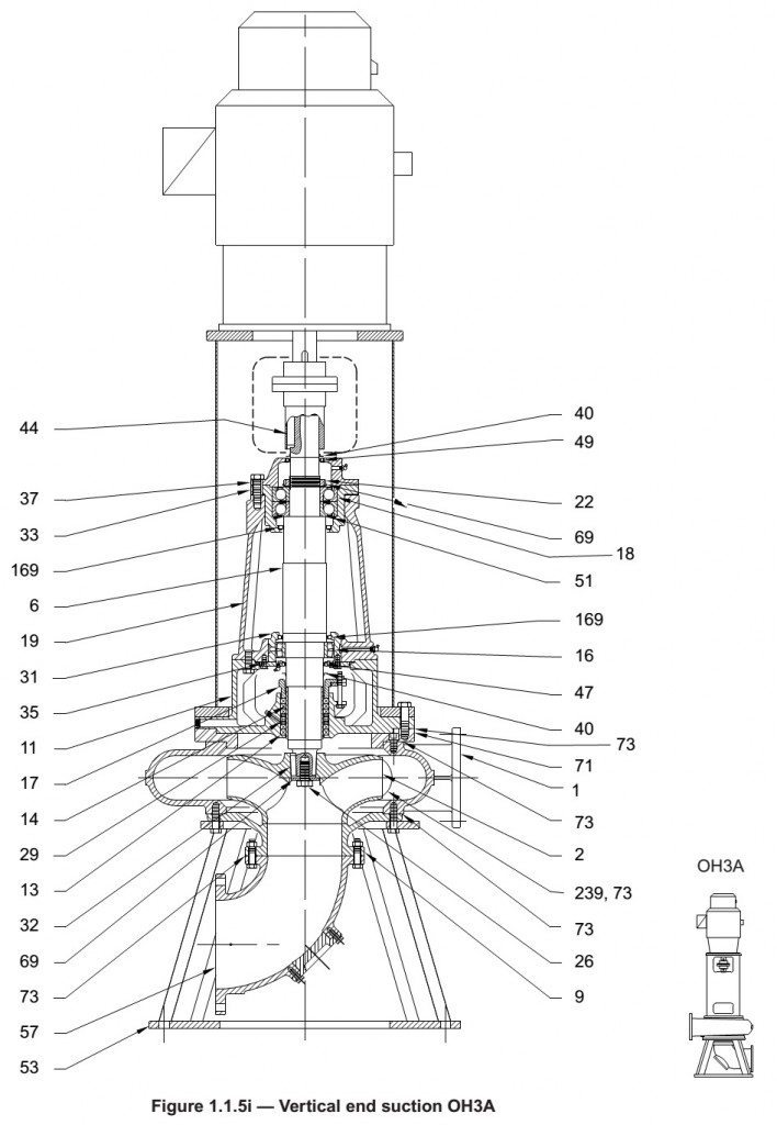
While mounting pump in a vertical arrangement makes pump removal more complicated, it does save on floorspace. As a result, solids-handling pumps are sometimes installed in a vertical arrangement with the motor positioned above the pump.
This installation arrangement has the added benefit of lifting the motor vertically, which provides a level of insurance against motor damage in the unlikely event that the pump room ever floods. In some cases, the motors are even installed ten or more feet above the pump and the two are connected by a length of universal-joint shafting.