Vertical turbines are commonly used in all types of applications, from moving process water in industrial plants to providing flow for cooling towers at power plants, from pumping raw water for irrigation, to boosting water pressure in municipal pumping systems, and for virtually every other imaginable pumping application. Turbines are one of the most popular types of pumps for designers, end-users, installing Contractors, and distributors.
Short-Set Vertical Turbine
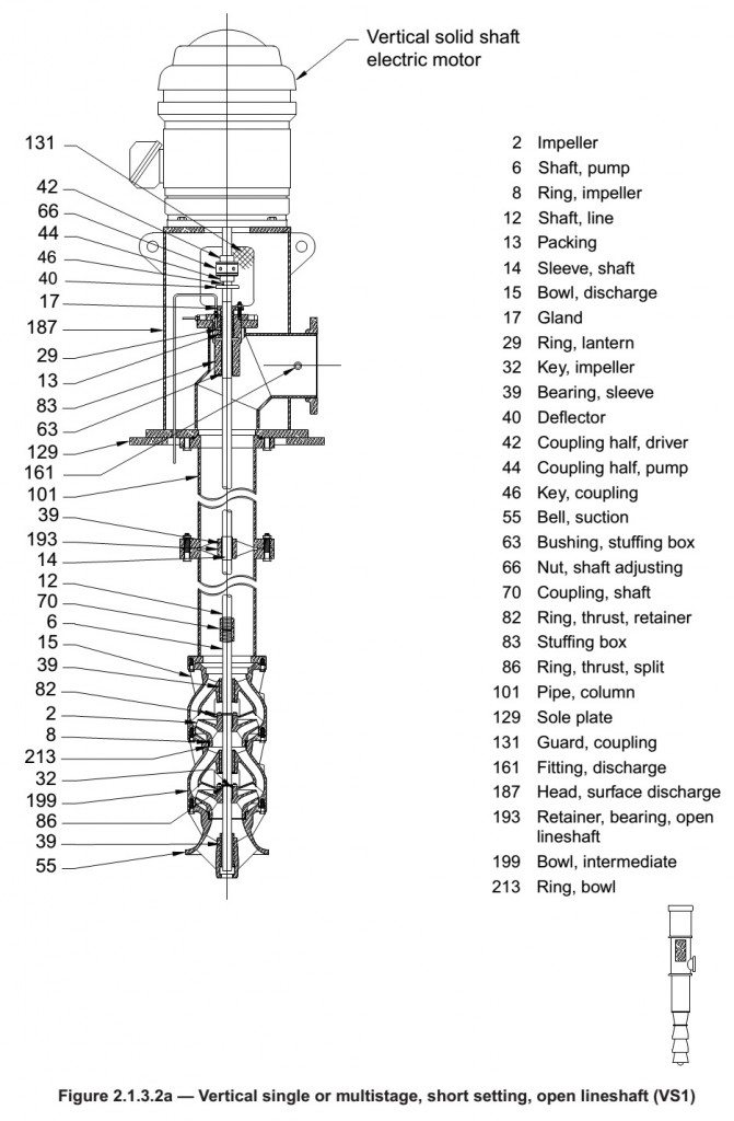
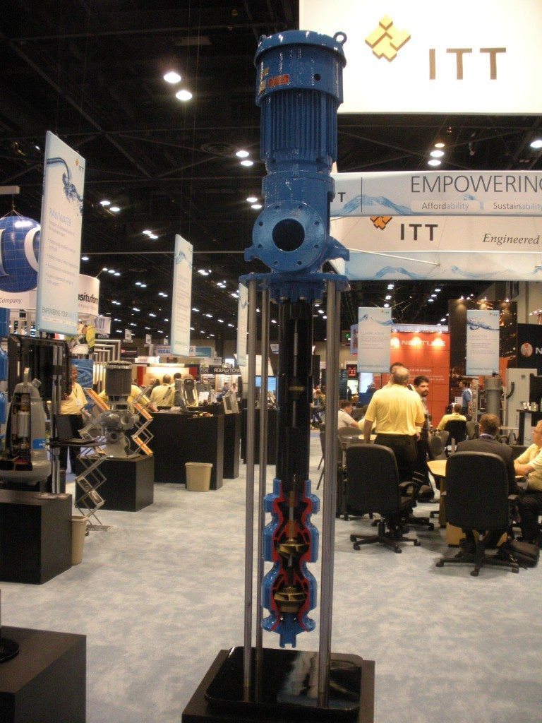
Short set turbines, typically designated as those shorter than 50′ in length though there is no formal definition, are common in all industries and applications. The pump bearings may be lubricated by the water being pumped, which is typically the case in relatively clean water applications, or they may be lubricated by an external water source, oil, or grease, in applications where the pumpage is not suitable for bearing lubrication.
When we talk about vertical turbine bearings, it’s important to realize that in North America most vertical turbines only have sleeve bearings which are not designed to carry any thrust or weight. Instead, the pump shaft is rigidly coupled to the motor shaft, and the motor bearings are designed to handle the weight of the shaft and impellers, as well as the downthrust generated while the pump is in operation.
The Bowl Assembly
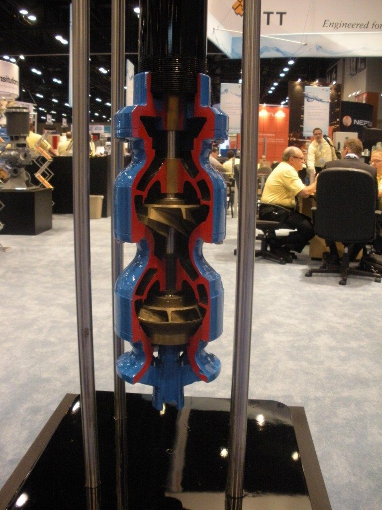
Vertical turbine pumps are often staged – that is, designed with more than one impeller. Each additional impeller increases the amount of head the pump can produce while the flow remains unchanged. For example, if a single-stage turbine (one with only one impeller) is designed to produce 1,000 Gallons per Minute (GPM) at 100 Feet Total Dynamic Head (Ft TDH), then adding a second identical stage will double the head the pump is capable of producing. So the two-stage unit would be capable of producing a flow of 1,000 GPM at 200 Ft TDH (100 Ft per stage).
When talking about a vertical turbine with two-stages, we would say that it has a “two-stage bowl assembly”. The bowl assembly of a vertical turbine consists of the suction case or bell, the impellers, and the diffuser-style casings. All of the impellers are mounted onto a single bowl shaft which passes up through the middle of the diffusers in which the impellers are arranged. There is one diffuser for each impeller. Taken together, an impeller and a diffuser combine to form a stage.
Turbines may be designed for as much pressure and as many stages as the pump manufacturer designed the bowls to be capable of withstanding. To demonstrate this principle, let’s expand on the theoretical pump we just mentioned.
Let’s imagine that the pump manufacturer has designed the pump bowls to be capable of withstanding pressures up to 300 PSI (approximately 694 Ft TDH). While each bowl will produce 100 Ft at the rated flow of 1,000 GPM, we also need to be carefuly to consider other conditions and to avoid exceeding the pressure capability of the pump at all of those conditions. In our example, the pump will be starting and stopping against a closed valve. In this condition the pump will operate a “dead head” or “shutoff” – the pressure produced when the pump isn’t producing any flow. For the sake of example, lets say that for a single-stage shutoff head is 150 Ft. Based on those figures we can come up with the following table:
| Stages | Head at Shutoff | Head at 1000 GPM |
|---|---|---|
| 1 | 150 | 100 |
| 2 | 300 | 200 |
| 3 | 450 | 300 |
| 4 | 600 | 400 |
| 5 | 750 | 500 |
As you can see, with 5 stages the shutoff head will exceed the capabilities of our pump (694 Ft). So in this simplified example, we are limited to a 4-stage pump. In actual practice we would customize the impellers by trimming them, and in so doing we would be able to use a modified 5-stage pump that came very near the maximum limitation of 694 Ft TDH.
Canned Vertical Turbine
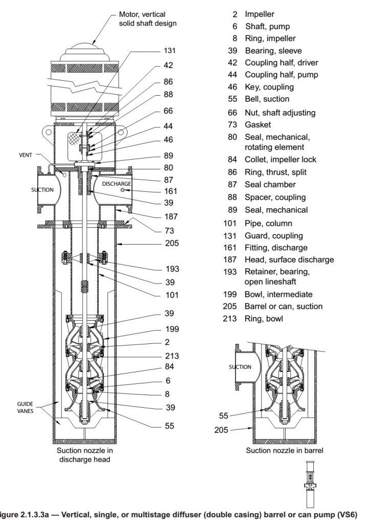
In some instances, vertical turbines are installed into individual cans or suction barrels. When this is done, the pumps are called “canned vertical turbines”, “barrel pumps”, or “can pumps”. Canned turbines are commonly used when pumping hydrocarbons. By doing so pump engineers and system designers can use gravity to increase the amount of suction pressure available to the pumps (NPSHa) to allow them to operate more effectively.
Canned pumps are also common in municipal water applications since the use of cans provides the designer with greater flexibility when designing a pump station.
Deep-Well Vertical Turbine
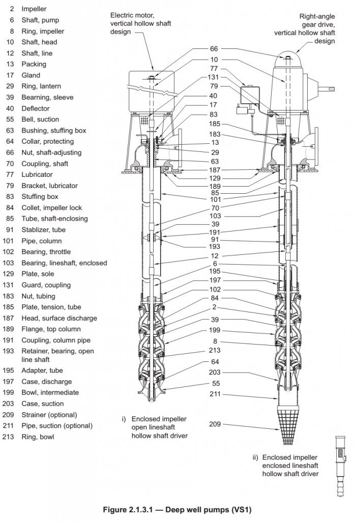
The use of vertical turbine pumps for well water is common. Deep-set well pumps range in length from around 100 feet all the way up to around 1,000 feet, and settings between 200 and 400 feet are common. Deep well pumps are used for irrigation water in many parts of the country, as well as for drinking water supply.
Mixed-Flow Vertical Turbine
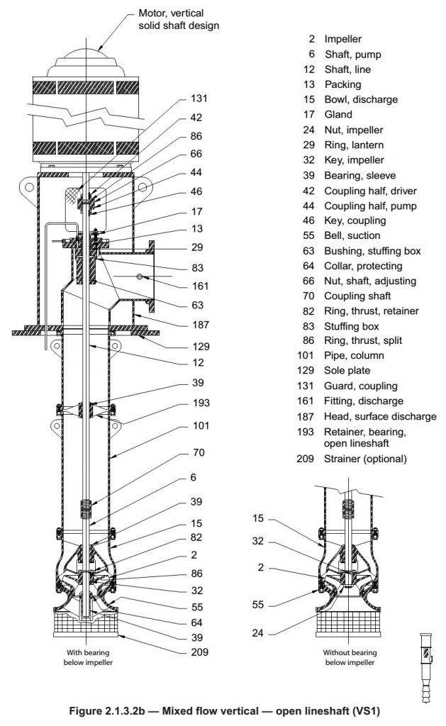
Mixed-flow vertical turbines are large vertical turbines used in municipal water supply, large-scale industrial applications, desalination applications, as well as flood control. Depending on the impeller design, mixed-flow impellers may be enclosed (such as those shown in the diagram) or open (similar to those shown in the axial-flow diagram below).
Enclosed-impeller mixed-flow turbines often have up to 3 or more stages and produce flows up to 30,000 GPM. Open mixed-flow impellers can be much larger – sometimes designed for flows in excess of 100,000 GPM, but are usually limited to just a single stage (though two-stage designs are occasionally seen).
Axial-Flow Vertical Pump
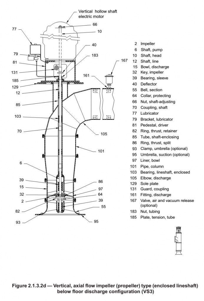
Axial-flow pumps are low-head high-flow designs and aren’t true turbines. However, from the outside looking in, axial-flow pumps look a lot like turbines, so we’ve included them in this category.
Axial-flow pumps are typically designed for heads no greater than approximately 30 Ft and are often designed to lift water just a dozen feet. They are common in flood-control applications and designed for flow ranging from a few thousand GPM up to hundreds of thousands of GPM (no, that’s no typo – I would know, I’ve sold them).
Submersible Turbine
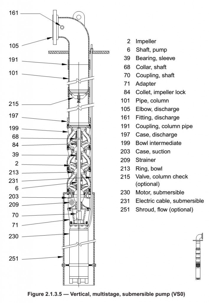
Submersible turbines incorporate a standard turbine bowl assembly with a submersible motor – a motor designed to operate submerged in water. The entire assembly is then bolted to the end of a length of pipe and lowered down into the well, lake, or river out of which water is to be drawn.
If you ever see a length of pipe rising out of a source of water, followed by an elbow, and additional piping, and you see a cable running down into the water, you are most likely looking at a submersible pump installation, and quite possible a submersible turbine installation.
There are several other types of submersible pumps that you can read more about.
Submersible turbines are common in deep well applications and are also used raw water pumps for irrigation, industrial plants, and municipal water supply.